1
Technical Documentation
De-Mystifying AutoCAD Plant 3D
Isometrics
Configuration Reference
4
Overview
AutoCAD Isometrics are a powerful tool that can boost your design production. This paper is going to introduce the core
concepts of AutoCAD isometrics, and expand on the setup to implement advanced features. We will cover options that are
available through the project setup dialog, explore creating a title block setup, learn how to test the isometric output,
expose features available only through the isoconfig.xml, and document a workflow for managing your isometrics.
5
2
Getting Started on AutoCAD Isometrics
2.1
Isometric Structure
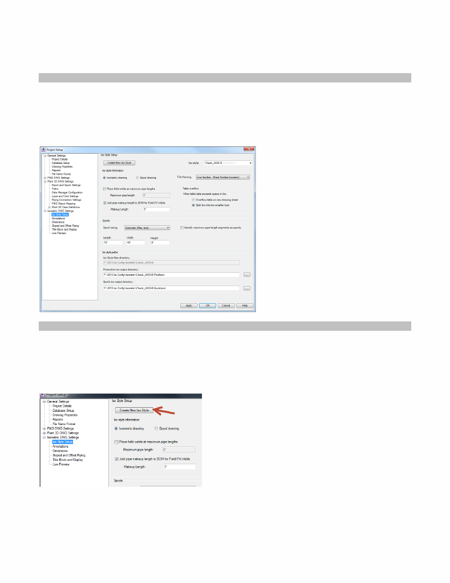
The isometric structure is centered on styles. Like dimension, annotation, and multi-leader styles, isometric styles
determine the color, layout, and structure of your isometrics. The default styles, Check, Final, Spool, and Stress, provide a
look at options you want to keep open for your styles.
Figure 1 Iso Style Settings
2.2
Creating a company style
2.2.1
Creating a new Style
To create a new style, click the Create New Iso Style button in the top left of the Iso Style Setup dialog.
Figure 2 Create new Iso Style button
Typically you create a new style if you want to use a specific style name, or you need to produce isometrics that look
different while preserving the default style options.
7
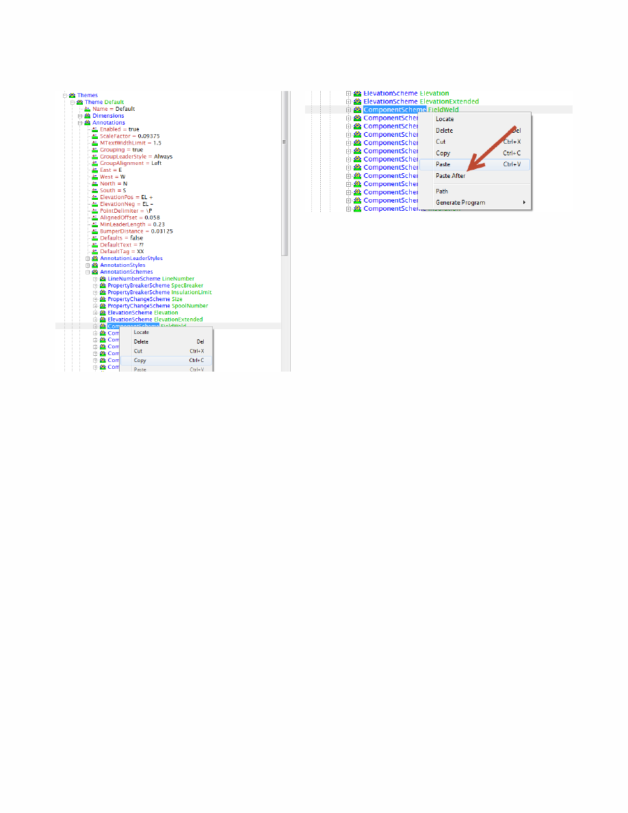
Figure 4 Copying a ComponentScheme
Figure 5 Duplicating a ComponentScheme
After duplicating the ComponentScheme, we need to modify it to place coordinates. Change the Name to PlaceCoords,
change the Format to “{0}”, Filter to “AnyItem”, Fields to “CO-ORDS”, and Placement to “Along”
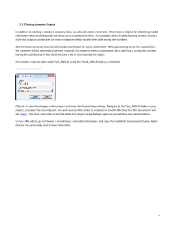
Save your changes and run a test iso. You should get output similar to this where every component has its coordinates
listed.